Circuit Descriptions Of The ICM

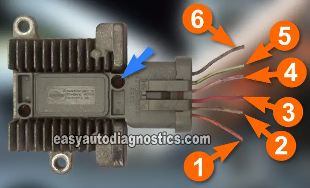
Here are brief descriptions of the circuits that we'll be testing. You'll notice that there are no wire color descriptions. This is intentional. The color of the wires in the illustration will not match the ones on your vehicle.
The good news is that no matter what color the wires are (on the vehicle), the circuit descriptions DO NOT CHANGE. You will be able to successfully diagnose this no-start condition with this information.
IMPORTANT: It will be necessary to test some of these circuits while the engine is being cranked. Be careful, use common sense and take all necessary safety precautions.
Ignition Control Module Connector
- Circuit 1
- Ground.
- Circuit 2
- Ignition Coil switching signal. This is the circuit that the ignition control module (ICM) uses to interrupt the primary current flowing thru' the ignition coil. This action is what causes the ignition coil to fire off spark.
- Circuit 3
- Power (12 V) with key on.
- Circuit 4
- START or IDM circuit. This is the circuit that the fuel injection computer uses to control ignition timing in conjunction with the SPOUT signal.
- Circuit 5
- SPOUT input. This is the circuit that the fuel injection computer uses to control ignition timing in conjunction with the START or IDM signals.
- Circuit 6
- PIP input (Profile Ignition Pickup Sensor Signal). This is the signal that both the ignition module and fuel injection computer use to know the piston positions to start fuel injection and spark, RPM, etc.
IMPORTANT: The module could be located on the left or right inner fender in the engine compartment. This could confuse you as to which wire is the #1 circuit. The rule of thumb is to take the first mounting bolt (see the BLUE ARROW on the figure above) nearest to the connector as a point of reference.
Ignition System Circuit Diagram Links
The following ignition system circuit diagrams will come in handy in troubleshooting the ignition control module.
1992-1995 Bronco, F150, F250, F350:
- Ignition System Wiring Diagram (1992-1993 Ford F150, F250, F350).
- Ignition System Wiring Diagram (1994-1995 Ford F150, F250, F350).
1992-1996 E150, E250, E350:
- Ignition System Wiring Diagram (1992-1993 Ford E150, E250, E350) (at: troubleshootmyvehicle.com).
- Ignition System Wiring Diagram (1994-1995 Ford E150, E250, E350) (at: troubleshootmyvehicle.com).
- Ignition System Wiring Diagram (1996 Ford E150, E250, E350) (at: troubleshootmyvehicle.com).
1992-1994 3.0L Ford Ranger:
TEST 1: Testing For Spark

Okay to get this show going, we need to see if the ignition system is creating and delivering spark to all 8 cylinders.
We need to find out if:
- All 8 spark plug wires are sparking.
- Or if only one (or two) of the 8 or not firing off spark.
Just a friendly reminder: Do not use a regular spark plug in place of a spark tester for the spark test. Also, do not pull the spark plug wire off of the spark plug while the engine is cranking (to check for spark). OK, let's start:
- 1
Remove the spark plug wire from its spark plug.
- 2
Attach the HEI spark tester (or an equivalent spark tester) to the spark plug wire.
- 3
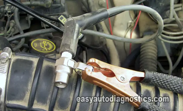
Attach the HEI spark tester to a good Ground point, or use a battery jump start cable to attach it to Ground (my preferred method).
- 4
Have your helper crank the engine while you observe the spark tester. You'll get one of two results: the spark tester will spark or it won't.
- 5
Repeat the test for all of the remaining spark plug wires.
Let's take a look at what your test results mean:
CASE 1: You got spark on all of the spark plug wires. This result indicates that the spark plug wires, distributor cap and rotor, ignition module, and ignition coil are working. You have eliminated these as the cause of your NO-START condition.
CASE 2: You got NO spark on none of the spark plug wires. This result doesn't condemn any specific component just yet.
The next step is to remove the spark plug wire that attaches to the middle tower of the distributor cap (this is the spark plug wire that comes from the ignition coil) to test for spark there. This test will directly test the ignition coil itself and thus eliminate the distributor cap as a possible source of the no-spark result. Go to: TEST 3: Testing For Spark At The Ignition Coil (Part 1).
CASE 3: You got spark on some but not all of the spark plug wires. More than likely the spark plug wires are bad or the distributor cap is bad.
It's a common problem for one or two spark plug wires to go bad or for one or two distributor cap towers to go bad and not let spark thru'. 90% of the time replacing the distributor cap, the distributor rotor and the spark plug wires should solve your problem, BUT to further test this, go to: TEST 2: Testing For Spark At The Distributor Cap.
