TEST 3: Testing The Continuity Of The WOT Circuit

If you've reached this point, you have: 1) Confirmed the throttle valve switch is getting power (TEST 1). 2) Confirmed that the 'idle' circuit of the TV switch is OK (TEST 2).
We are now gonna' check that the throttle valve (TV) switch's 'Wide Open Throttle' circuit is OK.
Testing the WOT circuit follows pretty much the same type of continuity tests you performed in TEST 2.
These are the test steps:
- 1
Disconnect the throttle valve switch from its connector and set your multimeter's function to Ohms mode.
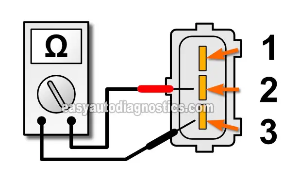
NOTE: Use the illustration above to identify the correct pins to test on the throttle valve switch itself. - 2
With the throttle plate in its fully open position, measure the resistance across pin #2 and pin #3 of the throttle valve (TV) switch as shown in the illustration above.
Your multimeter should show continuity (usually 5 Ohms or less). - 3
With the throttle plate in its closed position measure the resistance of pins #2 and pin #3 again.
Your multimeter SHOULD NOT register continuity (it should register OL). - 4
Repeat steps 2 through 3 several times just to make sure of your test results.
Let's find out what your specific multimeter test results mean:
CASE 1: Your multimeter registered the indicated continuity test results. This confirms that the 'WOT' circuit of the throttle switch is OK.
CASE 2: Your multimeter DID NOT register the indicated continuity test results. This tells you that the 'WOT' switch part of the throttle valve switch is defective. Replace the throttle valve switch.
Before replacing the throttle valve switch, I suggest that you make sure that its not mis-adjusted. For this procedure, go to: Adjusting the Throttle Valve Switch.
Adjusting The Throttle Valve Switch

The throttle valve switch has a to be adjusted when replaced (or if it has been mis-adjusted).
These are the factory manual steps:
- Start and warm up the engine till it reaches its normal operating temperature. Once warmed up, stop the engine.
- Place a .24" (.60 mm) feeler gauge between the throttle linkage lever and the throttle linkage stop screw (this throttle plate stop screw is on the throttle body).
- The throttle linkage lever is identified by the number 1 in the photo below.
- The throttle linkage stop screw is identified by the number 2 in the photo below.
- Unplug the throttle valve switch from its connector.
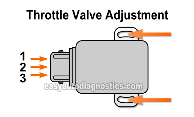
- With your multimeter in Ohms mode, continuity should exist between pin #1 and pin #2.
- If your multimeter does not indicate continuity then loosen the throttle valve adjustment screws and rotate the switch till your multimeter registers continuity.
- Tighten the TV switch adjustment screws to lock in the adjustment.
- Now, check continuity between pin #2 and pin #3 with the throttle plate in its wide open throttle (WOT) position. Your multimeter should register continuity.
- Reconnect the throttle valve switch to its connector and you're done.

More 2.6L Isuzu Diagnostic Tutorials
You can find a complete list of 2.6L Isuzu tutorials in this index: Isuzu 2.6L Index Of Articles.
Here's a small sample of the tutorials you'll find in the index:
- How To Test The Fuel Injectors (2.6L Isuzu Pick Up).
- 2.6L Isuzu MAF Sensor Test Amigo, Pick Up, Rodeo (1993-96).
- Blown Head Gasket Test Amigo, Pick Up, Rodeo (1993-96 Isuzu 2.6L).
- How To Test The Isuzu Manifold Absolute Pressure (MAP) Sensor.
- Engine Compression Test (2.6L Isuzu) Amigo, Pick Up, Rodeo (1993-96).

If this info saved the day, buy me a beer!


