TEST 2: Making Sure The MAF Sensor Is Getting Ground

In the previous test we checked that the Sensor was receiving 12 Volts. Now we'll check that the MAF sensor is getting a good Ground. This Ground is provided by the ECM internally.
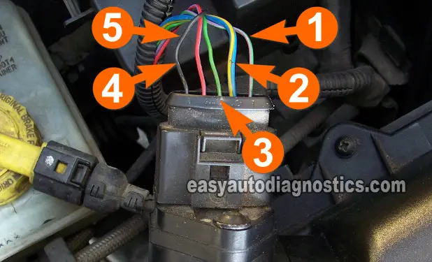
The wire that delivers this Ground to the MAF sensor is the one I've labeled with the number 3 in the photo above.
CAUTION: Be careful not to pass 12 Volts from the battery to this wire or you'll fry the fuel injection computer. The multimeter voltage test I'm suggesting in the instructions below is a safe way to test for the presence of Ground in the wire.
IMPORTANT: Be careful not to damage the connector's female terminals with the multimeter test lead.
OK, this is are the steps:
- 1
Disconnect the MAF sensor from its connector.
- 2
Put the multimeter in Volts DC mode.
- 3
Connect the red multimeter test lead to the battery positive (+) terminal.
- 4
Gently probe the terminal of the connector that connects to the wire identified with the number 3 with the black multimeter test lead.
- 5
Turn the key ON but don't crank or start the engine.
- 6
You should see 10 to 12 Volts on the multimeter.
Let's interpret your multimeter test results:
CASE 1: Your multimeter registered 10 to 12 Volts This confirms that the MAF sensor has a good path to Ground.
For the next test, go to: TEST 3: Making Sure The MAF Sensor Is Getting 5 Volts.
CASE 2: Your multimeter DID NOT register 10 to 12 Volts. Recheck all of your connections and repeat the test.
If still no 12 Volts, you'll need to find out the cause of this missing Ground, since without this Ground path, the MAF sensor will not function.
The most likely cause of this missing Ground is an open-circuit problem in the wire between the MAF sensor connector and the fuel injection computer's connector. Your next step is to find out what is wrong and resolve the issue.
TEST 3: Making Sure The MAF Sensor Is Getting 5 Volts

Now we'll check that the MAF sensor is receiving 5 Volts DC from the fuel injection computer.
The MAF sensor receives these 5 Volts from the wire that I've labeled with the number 4 in the photo above.
These are the test steps:
- 1
Disconnect the MAF sensor from its connector.
- 2
Put the multimeter in Volts DC mode.
- 3
Connect the black multimeter test lead to the battery negative (-) terminal.
- 4
Gently probe the terminal of the connector that connects to the wire identified with the number 4 with the red multimeter test lead.
- 5
Turn the key ON but don't crank or start the engine.
- 6
You should see 4.5 to 5 Volts on the multimeter.
Let's interpret your test result:
CASE 1: Your multimeter registered 5 Volts This confirms that the MAF sensor is getting 5 Volts from the computer.
For our last test, go to: TEST 4: Testing The MAF Signal.
CASE 2: Your multimeter DID NOT register 5 Volts Recheck all of your connections and repeat the test. If still no 5 Volts, the MAF sensor is not the problem. Without this 5 Volt Reference Voltage the MAF sensor will not work.
The most likely cause of these missing 5 Volts is an open-circuit problem in the wire between the MAF sensor connector and the fuel injection computer's connector. Your next step is to find out what is wrong and resolve the issue.
TEST 4: Testing The MAF Signal

Now that the basics have been checked, we'll check the MAF signal coming out of the sensor and going to the ECM.
The beauty of this test is that you don't need a scan tool to do it. The same multimeter you've been using so far should suffice.
Start the engine and let it reach it's normal operating temperature. You'll be using the voltage reading you will obtain at idle as a base to diagnose the MAF sensor.
IMPORTANT: The MAF sensor must be connected to its connector to perform this test. You'll need to use a back-probe on the connector or a wire-piercing probe on the wire to access the signal within the wire. You can see an example of this tool and where to buy it here: Wire Piercing Probe.
- 1
Connect the red multimeter test lead to the wire labeled with the number 5 shown in the photo.
- 2
Put your multimeter in Volts DC mode.
- 3
Connect the black multimeter test lead to the battery negative (-) terminal.
- 4
Start the already warmed up engine.
- 5
Note the Volts reading on your multimeter at idle. This reading may be stable (with only small fluctuations) or unstable with very extreme fluctuations. No matter what the instability in the reading, this will be your base reading.
- 6
Accelerate the engine as you watch the multimeter's voltage readings.
The MAF signal voltage value should increase as you rev up the engine. - 7
Let the engine return to idle.
The MAF signal voltage value should decrease as the engine returns to idle. - 8
The voltage value should rise/fall every time you rev up/down the engine.
If the MAF sensor is defective, the MAF signal voltage value will stay stuck in one single number as you rev up/down the engine.
Did the signal rise smoothly with each increase in engine acceleration and stay steady at idle?
CASE 1: Your multimeter registered the indicated voltages This confirms that the MAF sensor is functioning correctly and not the cause of the issue.
CASE 2: Your multimeter DID NOT register the indicated voltages Recheck all of your connections and repeat the test.
If your multimeter still does not register the indicated voltages, you can conclude that the MAF sensor is bad and needs to be replaced if you have:
- Confirmed that the MAF sensor is getting 12 Volts (TEST 1).
- Confirmed that the MAF sensor is getting Ground (TEST 2).
- Confirmed that the MAF sensor is getting 5 Volts (TEST 3).
- In this test section, confirmed that the MAF signal is stuck in one value regardless of engine RPM.
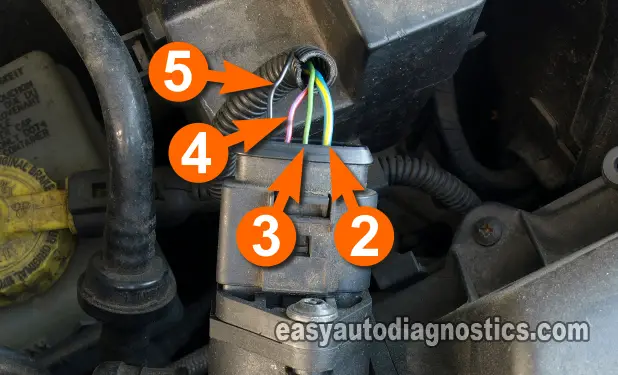
MAF Sensor With 5 Slot Connector With 4 Wires

The above is an example of the 5 terminal Bosch MAF sensor that has slots for 5 wires, but has only 4. This test tutorial applies to this type of MAF sensor.

If this info saved the day, buy me a beer!

