TEST 4: Making Sure The ICM And CKP Sensor Are Getting Ground

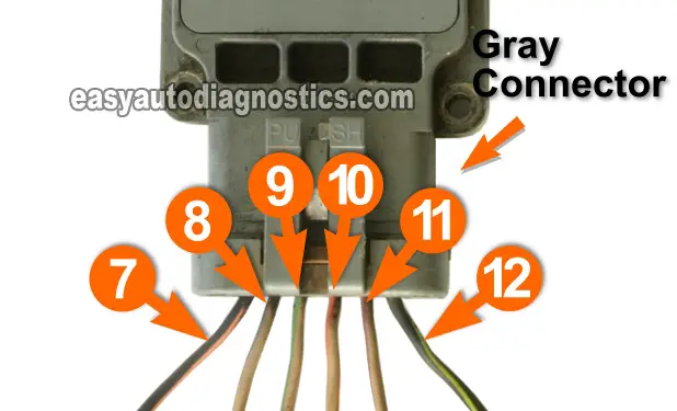
In this test section, we'll check that the wire that connects to the number 7 terminal of the bottom ICM connector has chassis Ground.
To check for the presence of Ground in the wire that connects to terminal number 7, we'll do a simple voltage test with a multimeter.
IMPORTANT: The Ground, we're checking for in the number 7-wire is provided by the ICM (internally). Therefore, this test must be done with the bottom ICM connector connected to the ICM and the ICM bolted to the intake manifold.
OK, to start this test, this is what you need to do:
- 1
Set your multimeter to Volts DC mode.
- 2
Connect the black multimeter lead to the wire labeled with the number 7 of the bottom ICM connector using the appropriate tool.
NOTE: If you need to disconnect the bottom connector to attach the multimeter test lead, be sure and reconnect it before proceeding to the next step. - 3
Connect the red multimeter test lead directly to the positive (+) battery post.
- 4
Your multimeter should register 10 to 12 Volts.
OK, let's interpret your test results:
CASE 1: Your multimeter showed 10 to 12 Volts. This is the correct and expected test result and confirms that the ignition control module and crankshaft position sensor have a good Ground connection.
The next step is to check that the crankshaft position sensor is producing both its CKP and CID signals. For the first test (of two), go to: TEST 9: Testing The CKP Signal With A Multimeter.
CASE 2: Your multimeter DID NOT show 10 to 12 Volts. Recheck all of your multimeter connections and repeat the test one more time.
If after repeating the test, your multimeter still does not show 10 to 12 Volts, the ICM is not providing a Ground. In my experience, this usually happens because one of the bolts (that attaches the ICM to the intake manifold) is missing.
ICM terminal number 7 is connected (internally) to the bottom ignition control module mounting holes and these metal mounting holes are the Ground source.
Installing the missing bolts and/or repairing this missing Ground issue will resolve the no-spark no-start condition on your 2.3L Ford Ranger (Ford Mustang, Mazda B2300).
TEST 5: Checking For Spark Directly On The 1/4 Ignition Coil Towers (Exhaust Side)
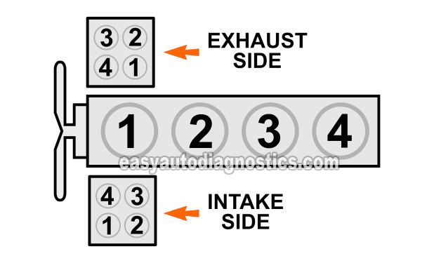
In this test section, we'll check for spark directly at the ignition coil towers for cylinders 1 and 4 (exhaust side spark plugs).
In order to get the correct result from this test, it is important that you perform this test with a spark tester.
If you don't have one, I recommend the HEI Spark Tester and you can buy one here: OTC 6589 Electronic Ignition Spark Tester (at: amazon.com).
NOTE: To perform this test, you'll need to crank the engine. Be careful and take all necessary safety precautions!
OK, to start this test, this is what you need to do:
- 1
Disconnect the spark plug wire from the cylinder 1 ignition coil tower.
NOTE: This test is performed on the exhaust side ignition coil pack. - 2
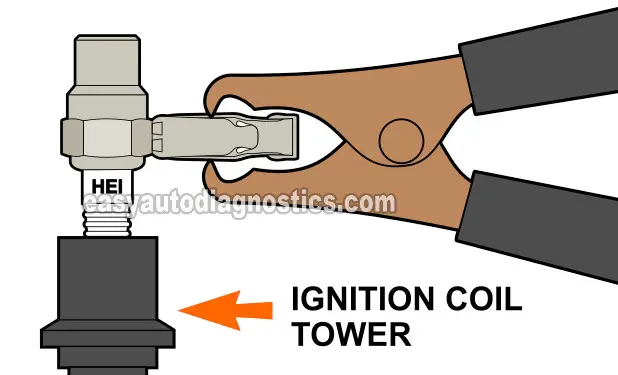
Place your spark tester in the ignition coil tower (see the illustration above).
- 3
Ground the spark tester directly on the battery negative (-) post using a jump-start cable.
- 4
Have your helper crank the engine while you observer the spark tester.
- 5
The spark tester should spark.
- 6
Repeat steps 1 through 5 on the cylinder 4 ignition coil tower.
OK, let's interpret your test results:
CASE 1: The spark tester sparked. This test result tells you the spark plug wires are bad.
Replace all of the spark plug wires if you have:
- Confirmed that the exhaust side spark plug wires for cylinders 1 and 4 ARE NOT sparking (TEST 1).
- Confirmed that the exhaust side ignition coil pack towers for cylinders 1 and 4 are sparking (this test section).
Replacing all of the spark plug wires should solve the issue.
CASE 2: The spark tester DID NOT spark. This test result eliminates the spark plug wires as bad, since the ignition coil towers are not sparking.
Your next step is to check the ignition coil pack is getting the 1/4 ignition coil control signal. Go to: TEST 11: Cylinders 1 And 4 Activation Signal (Exhaust Side).
TEST 6: Checking For Spark Directly On The 2/3 Ignition Coil Towers (Exhaust Side)
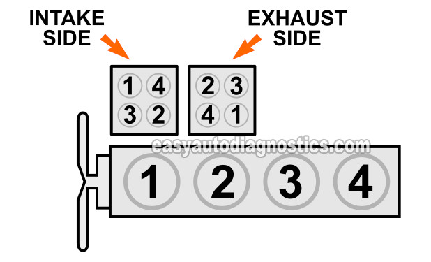
In this test section, we'll check for spark directly at the ignition coil towers for cylinders 2 and 3 (exhaust side spark plugs).
In order to get the correct result from this test, it is important that you perform this test with a spark tester.
If you don't have one, I recommend the HEI Spark Tester and you can buy one here: OTC 6589 Electronic Ignition Spark Tester (at: amazon.com).
NOTE: To perform this test, you'll need to crank the engine. Be careful and take all necessary safety precautions!
Let's get started:
- 1
Disconnect the spark plug wire from the cylinder 2 ignition coil tower.
NOTE: This test is performed on the exhaust side ignition coil pack. - 2
Place your spark tester in the ignition coil tower (see the illustration above).
- 3
Ground the spark tester directly on the battery negative (-) post using a jump-start cable.
- 4
Have your helper crank the engine while you observer the spark tester.
- 5
The spark tester should spark.
- 6
Repeat steps 1 through 5 on the cylinder 3 ignition coil tower.
OK, let's interpret your test results:
CASE 1: The spark tester sparked. This test result tells you the spark plug wires are bad.
Replace all of the spark plug wires if you have:
- Confirmed that the exhaust side spark plug wires for cylinders 2 and 3 ARE NOT sparking (TEST 1).
- Confirmed that the exhaust side ignition coil pack towers for cylinders 2 and 3 are sparking (this test section).
Replacing all of the spark plug wires should solve the issue.
CASE 2: The spark tester DID NOT spark. This test result eliminates the spark plug wires as bad, since the ignition coil towers are not sparking.
Your next step is to check the ignition coil pack is getting the 2/3 ignition coil control signal. Go to: TEST 12: Cylinders 2 And 3 Activation Signal (Exhaust Side).


