This test will help you to pinpoint the problem to the ignition control module (ICM) or the crankshaft position sensor as the source of your car's no-start condition. Before starting the tests you must first check and verify that there's NO SPARK present at any of the coil towers.
Why? Because the clearest indication that the ignition control module and the crankshaft position sensor are good is if there's spark coming from all of the spark plug wires. So if you haven't checked, stop now and do a spark test on all of the spark plug wires.
Contents of this tutorial:
- How The 3.8L Ignition Control Module (ICM) Works.
- The GM 3.8L 3X CKP And 18X CKP Sensors.
- What Will I Test?
- What Tools Do I Need?
- Do's And Don'ts And Safety Precautions.
- Circuit Descriptions Of The Ignition Module.
- TEST 1: Checking For Power (12 V).
- TEST 2: Testing The Ground Circuit.
- TEST 3: Making Sure The Crank Sensor Is Getting Power.
- TEST 4: Verifying The 18X CKP Sensor Signal.
- TEST 5: Verifying The 3X CKP Sensor Signal.
- Where To Buy The ICM And Save.
- In Closing.
- Real Life Case Studies From easyautodiagnostics.com Readers.
- Real Life Case Study 1.
![]() You can find this tutorial in Spanish here: Cómo Probar El Módulo De Encendido Y Sensor Del Cigüeñal GM 3.8L (at: autotecnico-online.com).
You can find this tutorial in Spanish here: Cómo Probar El Módulo De Encendido Y Sensor Del Cigüeñal GM 3.8L (at: autotecnico-online.com).
NOTE: If you do need to test just the ignition coil packs sitting on top of the ignition control module (ICM), here's the article for you:
For a list of all of the 3.8L articles in this site, check out the index:
How The 3.8L Ignition Control Module (ICM) Works
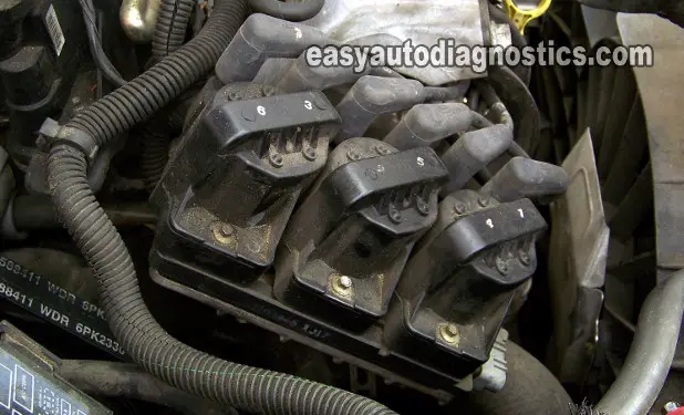
Here is a little background information to help you diagnose this no-spark condition. In a nutshell, when the system is working properly, at crank-up and below 400 RPMs the ignition control module controls spark (by activating the three ignition coils that sit on top of it) without help from the fuel injection computer.
More specifically:
- When you turn the key to start the engine, the ignition control module gets power (12 Volts) and Ground.
- Once the ICM gets power, it in turn supplies power to:
- The crank sensor.
- The cam sensor (if equipped).
- The 3 ignition coil packs sitting on top of it.
- As the engine cranks, the ignition module receives the crank sensor signal.
- The crank sensor signal is an ON/OFF type of signal that can be measured with a multimeter or an LED light.
- The crank sensor signal is also called the 'triggering signal' in this article.
- As soon as the ICM gets the crank sensor signal, it starts activating the ignition coils sitting atop of it.
- The ignition control module does this by switching the ignition coils' primary current ON and OFF in a base timing mode so that they'll start sparking away.
- This ON/OFF signal is referred to as the switching signal thru' out the article.
- The ICM also sends a Fuel Control signal to the PCM (Powertrain Control Module = Fuel Injection Computer).
- The PCM uses this signal to start activating the fuel injectors.
- Once the engine starts and/or above 400 RPMs (anything above this and the computer considers the engine as having started), the ECM takes over spark timing and the activation of the ignition coils (thru' the ignition control module of course).
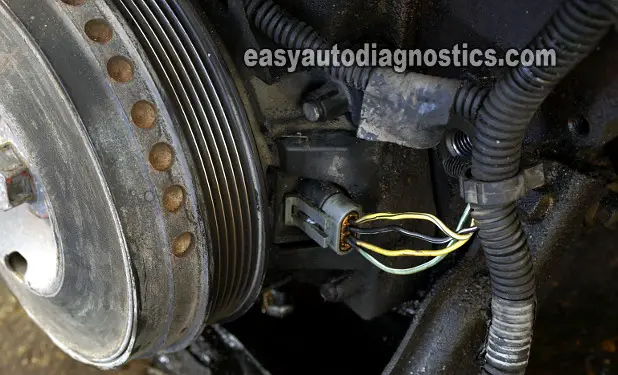
When does the ignition control module (ICM) create this switching signal? After receiving 12 Volts, Ground, and the Triggering signals from the crankshaft position sensor assembly (which is located behind the crankshaft pulley).
The GM 3.8L 3X CKP And 18X CKP Sensors

The crankshaft position sensor is two hall effect sensors in one. In other words, the assembly is two crank sensors in one and in this article, I'll also show you how to test it.
One CKP sensor is called the 3X CKP sensor and the signal it creates is called the Sync 3X CKP Signal and the other one is called the 18X CKP and its signal the Crank 18X CKP Signal. As stated before, both of these signals are critical for the ignition control module to start the car (to start sparking the ignition coils).
Although an oscilloscope is the best way to check for the pulses from the crankshaft position sensor (3X CKP and 18X CKP) to the ignition control module, there's another way that I've used successfully for a number of years. This is using an LED light.
This LED light you can buy from any electronics store ( I buy mine from my local Radio Shack store). If you're curious as to what this LED light looks like and how to make it, click here: The LED Light Test Tool And How To Make One.
If you have access to an oscilloscope, I have included photos of what the wave-forms should look like. Whether you use the LED light, or a multimeter, or an oscilloscope, you'll be able to successfully diagnose this no-start condition! So, read on my friend.
What Will I Test?
The ignition module test is a very straightforward and simple test. This is what it's composed of:
- The first order of business is to make sure the ICM is getting power and Ground.
- Then, you'll make sure that the crank sensor is also getting juice.
- The next step is to test the crank sensor signals.
- Remember, there are two signals involved (in starting the engine) and that are produced by the same crank sensor.
- From the results you get you'll be able to pinpoint the problem to
- The ignition control module.
- The crankshaft position sensor.
Or completely eliminate these as the cause of the no-start condition.
As you can see from the above test summary, it's that easy to test the ignition control module!
IMPORTANT- To perform all of the tests the battery MUST be in a fully charged condition.
What Tools Do I Need?
The really cool thing about testing this type of ignition control module (ICM) and crankshaft position sensor (CKP) is that you can use some very simple and inexpensive tools. Here's the basic list:
- A multimeter.
- Either a digital multimeter or an analog multimeter can be used (don't have a digital multimeter? Need to buy one? Click here to see my recommendations: Buying A Digital Multimeter For Automotive Diagnostic Testing).
- An LED light.
- You can buy this bad boy at any auto parts store (like Auto Zone, O'Reilly Auto Parts, Pepboys). You can see an example of one here and you can also buy it here: Abe's LED Light Test Tool.
- 12 Volt test light.
- When testing for power (12 Volts), you can use the test light instead of a multimeter.
- Wire piercing probes.
- These tools are time savers and not only that, will help you to keep from peeling too much from the wire to test whatever signal runs thru' it.
- If you've never seen one of these tools, click here: Wire Piercing Probe.
- A repair manual.
- There's some stuff that this article does not cover, like the actual remove and replace of the components you're gonna' test. This is where a repair manual will come in super handy.
- Someone to help you crank the vehicle.
Do's And Don'ts And Safety Precautions
Anything to do with working on or around a car is dangerous. Since some of the tests in this article are done with the engine cranking, it goes without saying that you have to be alert, extra careful and use common sense to perform them.
Whomever is gonna' help you crank the vehicle, while you observe the multimeter, has to wait outside of the car or minivan until after you've connected your connections and you're clear of the engine. After the test is done and you don't need your helper to crank the engine anymore... have him or her step out of the vehicle. Taking these safety precautions may save you from any unfortunate accident that may happen if said helper thinks he (or she) heard you say "crank it".
