TEST 1: Spark Test

Whether your Mitsubishi car (or Chrysler Sebring or Dodge Stratus) starts or not, this will be the starting point for all of your tests.
As mentioned before, the successful outcome of your trouble-shooting/diagnostic lies in the usage of an HEI spark tester (don't have an HEI spark tester? Need to buy one? You can buy it here: OTC 6589 Electronic Ignition Spark Tester).
Now, if you only need to test the crankshaft position (CKP) sensor, your starting point is here: TEST 7: Making Sure The Crankshaft Position Sensor Is Getting Power.
IMPORTANT: As you may already know, each ignition coil feeds spark to two cylinders:
- Cylinders #1 and #3 are fed spark thru' a spark plug wire (high tension wire).
- Cylinders #2 and #4 are fed spark directly by the ignition coils' boots.
Keeping this in mind, when testing for spark at the ignition coil's boot, the spark plug wire has to remain connected to the ignition coil and when testing for spark at the spark plug wire, the ignition coil has to remain bolted in its place on the valve cover. The following test steps assume that you're gonna' start by testing from the #1 cylinder:
- 1
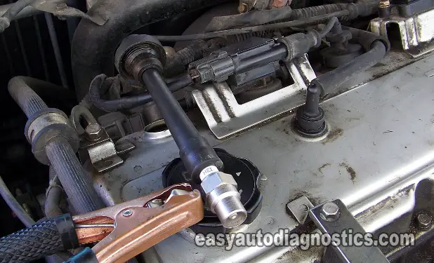
Remove the spark plug wire (high tension cable) from the #1 cylinder spark plug and attach the spark tester to it (all the other components must remain connected and in their places).
- 2
Ground the spark tester with a battery jump start cable as shown in the photo above.
- 3
Have your helper crank the engine.
The engine may or may start, either way be careful. - 4
You're gonna' get one of two results: spark or no spark.
- 5
Remove the HEI spark tester from the spark plug wire and reconnect the spark plug wire back to its spark plug.
- 6
Now, remove the ignition coil for cylinder #2 and attach the HEI spark tester to the ignition coil's boot. The ignition coil has a spark plug wire connected to it (this wire feeds spark to cylinder #3) and it must remain connected to it as you test for spark on the boot.
- 7
Have your assistant crank the engine once again while you observe the HEI spark tester.
- 8
Repeat these tests on the remaining cylinders (#3 and #4) following the procedures outlined in steps 1 to 7 of this test.
IMPORTANT: Read each of the following test result cases carefully to see which one matches the result of your spark test, since the following result interpretations take into account if the no spark results were obtained from a spark plug wire or directly from the ignition coil boot:
CASE 1: You got spark from all cylinders. This is the correct test result and indicates that the ignition coils and spark plug wires are OK. The cause of your misfire condition is not due to a bad ignition coil.
If your Mitsubishi engine is still misfiring, take a look at this section: Misfire Due To Carbon Tracks.
CASE 2: You got NO spark from a spark plug wire. This lack of spark will cause a cylinder misfire.
The next step is to remove the spark plug wire from its ignition coil tower and test for spark directly on the ignition coil tower. For this test go to: TEST 5: Testing For Spark At The Ignition Coil Spark Plug Wire Tower.
CASE 3: Cylinder #2 is NOT getting spark. This lack of spark will cause a cylinder misfire.
You can conclude that the ignition coil is bad if the spark plug wire of cylinder #3 is firing spark. You can conclude this because cylinder #2 and cylinder #3 receive spark from the same ignition coil. And this spark is fed to these two cylinders at the same time. If cylinder #3 is the only one receiving spark from the ignition coil, then the ignition coil is defective.
CASE 4: Cylinder #4 is NOT getting spark. This lack of spark will cause a cylinder misfire.
You can conclude that the ignition coil is bad if the spark plug wire of cylinder #1 is firing spark. You can conclude this because cylinder #1 and cylinder #4 receive spark from the same ignition coil. And this spark is fed to these two cylinders at the same time. If cylinder #1 is the only one receiving spark from the ignition coil, then the ignition coil is defective.
CASE 5: The ignition coil that supplies spark to cylinders #1 and #4 is NOT firing spark to these 2 cylinders. The next step is to verify that this ignition coil is receiving 12 Volts, Ground and its activation signal. Go to: TEST 2: Testing The Power (12 V) Circuit.
CASE 6: The ignition coil that supplies spark to cylinders #2 and #6 is NOT firing spark to these 2 cylinders. The next step is to verify that this ignition coil is receiving 12 Volts, Ground and its activation signal. Go to: TEST 2: Testing The Power (12 V) Circuit.
CASE 7: Both ignition coils are NOT firing spark to all 4 cylinders. This usually indicates that the crankshaft position sensor is defective.
To test the crankshaft position sensor go to: TEST 6: Making Sure The Crankshaft Position Sensor Is Getting Power.
TEST 2: Testing The Power (12 V) Circuit

The ignition coil needs power in the form of 12 Volts to be able to create and feed spark and in this test step you'll verify this voltage using a multimeter (you can also use a 12 Volt test light).
I recommend that you test for this voltage with the ignition coil connected to its connector and with a wire-piercing probe to get to the signal within the wire (you can see an example of this tool here: Wire-Piercing Probe). Now, if you decide to unplug the connector to test the front of the female terminal (of the connector) for 12 Volts so be careful not to damage it.
These are the test steps:
- 1
Disconnect the ignition coil from its connector.
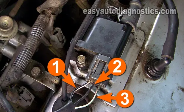
The three wires in the ignition coil's connector are usually sheathed in a hard plastic tube, remove enough of this plastic tube to expose the three wires for testing. - 2
Put the multimeter in Volts DC mode.
- 3
Probe the circuit labeled with the number 1 (see photo above) with the red multimeter test lead (using an appropriate tool to pierce the wire).
- 4
Connect the black multimeter test lead to the battery negative (-) terminal.
- 5
Have your helper turn the key to the ON position.
- 6
You should see 10-12 Volts on your multimeter or if you're using a test light, the test light should light up.
Let's take a look at what your test results mean:
CASE 1: The multimeter registered 10-12 Volts (or the test light lit up). This test result tells you the power circuit is OK and is delivering voltage.
The next step is to test the Ground circuit, go to: TEST 3: Testing The Ground Circuit.
CASE 2: The multimeter DID NOT register 10-12 Volts (or the test light DID NOT light up). The ignition coil will not fire off spark if it's missing these 10 to 12 Volts.
The next step is to repair the cause of these missing 10 to 12 Volts. The ignition coil will spark again once this voltage is restored to it.
TEST 3: Testing The Ground Circuit

The ignition coil on your Mitsubishi vehicle also needs Ground to be able to function. This test can also be accomplished with the ignition coil connected or disconnected to its connector.
These are the test steps:
- 1
Put the multimeter in Volts DC mode.
- 2
Probe the circuit labeled with the number 2 (see photo above) with the black multimeter test lead (using an appropriate tool to pierce the wire).
- 3
Connect the red multimeter test lead to the battery positive (+) terminal.
- 4
Have your helper turn the key to the ON position.
- 5
You should see 10-12 Volts on your multimeter or if you're using a test light, the test light should light up.
Let's examine your test result:
CASE 1: The multimeter registered 10-12 Volts (or the test light lit up). This is the correct test result and lets you know that the ignition coil is getting Ground.
The next step is to make sure that the ignition coil is getting an activation signal. Go to: TEST 4: Triggering Signal Test.
CASE 2: The multimeter DID NOT register 10-12 Volts (or the test light DID NOT light up). The ignition coil will not fire off spark if it's missing Ground.
The next step is to repair the cause of this missing Ground. The ignition coil will spark again once Ground is restored to it.
