

The crankshaft position (CKP) sensor can be tested with nothing more than a multimeter. Yup, no scan tool is required for the actual sensor tests!
In this tutorial, I'm going to show you how to check the CKP sensor's 58X output signal and make sure it's receiving both power and Ground. All three of these tests are done with a multimeter.
With your test results, you'll easily find out if the sensor is toast or if there's a problem with its power, Ground, signal circuit, or wiring.
Contents of this tutorial:
- Symptoms Of A Bad CKP Sensor.
- Circuit Descriptions Of The Crankshaft Position Sensor.
- Important Safety Precautions And Tips.
- TEST 1: Testing The CKP Signal.
- TEST 2: Making Sure The CKP Sensor Has Power.
- TEST 3: Making Sure The CKP Sensor Has Ground.
- More 2.2L Isuzu Rodeo And Amigo Diagnostic Tutorials.
ES  You can find this tutorial in Spanish here: Cómo Probar El Sensor De Posición Del Cigüeñal (1998-2003 2.2L Isuzu Rodeo, Amigo) (at: autotecnico-online.com).
APPLIES TO: This tutorial applies to the following vehicles:
- 2.2L Isuzu Amigo: 1998, 1999, 2000.
- 2.2L Isuzu Rodeo: 1998, 1999, 2000, 2001, 2002, 2003.
CKP SENSOR CIRCUIT WIRING DIAGRAMS:
RELATED TUTORIALS: The following tutorial will help you test the ignition coil pack/ignition control module assembly and camshaft position (CMP) sensor:
- How To Test The Ignition Coil Pack (1998-2003 2.2L Isuzu Rodeo, Amigo).
- How To Test The CMP Sensor (1998-2003 2.2L Isuzu Rodeo, Amigo).
Symptoms Of A Bad CKP Sensor
The crankshaft position (CKP) sensor helps the PCM keep track of the crankshaft's exact position as the engine turns. It does this by producing 58 digital pulses for every revolution of the crankshaft.
The PCM uses the CKP signal to determine crankshaft position and engine speed. With this info (along with the CMP sensor signal), it can control and fine-tune fuel injection and ignition timing as the engine cranks and runs.
When the CKP sensor, its power supply, Ground circuit, signal circuit, or wiring develops a problem, the engine isn't gonna run correctly or may not start at all.
You may notice one or more of the following symptoms:
- Engine no-start: The engine may crank normally but fail to start because the PCM isn't receiving a valid CKP signal.
- Intermittent stalling: The engine may suddenly stall if the CKP signal drops out while you're driving.
- Rough running: An interrupted or unstable CKP signal may cause the engine to run unevenly.
- Check engine light: The PCM may store a crankshaft position sensor diagnostic trouble code.
Keep in mind that these symptoms can also be caused by problems with the sensor's 5-volt supply, Ground circuit, signal wire, connector, or wiring harness.
That's why we can't condemn the CKP sensor based on symptoms alone. We've got to test the circuits and verify that the sensor is producing its 0-to-5-volt switching signal.
The good news is that these tests can be performed with a multimeter. No scan tool is required to check the sensor's power, Ground, or signal.
Circuit Descriptions Of The Crankshaft Position Sensor
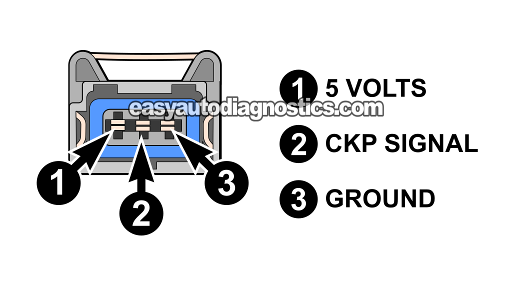
The CKP sensor on your 2.2L Isuzu Rodeo or Amigo is a 3-wire, 5-volt digital sensor. For it to produce a crankshaft position signal, it needs two things: a 5-Volt power supply and Ground.
NOTE: The CKP sensor has male terminals, while the engine wiring harness connector has female terminals.
The following table identifies each female terminal of the CKP sensor connector:
| CKP Sensor Connector | ||
|---|---|---|
| Terminal | Wire Color | Description |
| 1 | Green (GRN) | 5-Volt Supply |
| 2 | Blue (BLU) | CKP Signal |
| 3 | Black with blue stripe (BLK/BLU) | Chassis Ground |
CKP SENSOR CIRCUIT WIRING DIAGRAMS:
Important Safety Precautions And Tips
TIP 1: All of the tests in this tutorial are performed with the CKP sensor installed on the engine. There's no need to remove the sensor.
TIP 2: When checking the CKP sensor signal, rotate the engine by hand. The easiest way to do this is with a 1/2-inch ratchet and the correct socket on the crankshaft pulley bolt.
Rotate the crankshaft slowly. This gives your multimeter enough time to display the sensor's signal switching between approximately 0 and 5 volts.
Don't use the starter motor during TEST 1. The engine will turn too quickly, and your multimeter may only display an average reading of approximately 2.5 volts.
TEST 1: Testing The CKP Signal
Our first test is going to verify that the CKP sensor is switching its output voltage between ON and OFF as the crankshaft rotates.
Here's what you should see on your multimeter:
- ON: The CKP signal switches to approximately 5 Volts DC.
- OFF: The CKP signal drops to approximately 0 Volts.
To observe this ON/OFF signal, you'll need to rotate the engine very slowly by hand. Don't use the starter motor, since it'll turn the engine too fast for a regular multimeter to display the voltage changes correctly.
If the CKP sensor is fried, its output signal (on the BLU wire) will usually stay stuck at one voltage as you rotate the engine by hand. In other words, the signal won't switch back and forth between approximately 0 and 5 Volts.
LOCATION OF THE CKP SENSOR: The CKP sensor is located behind the crankshaft pulley.
IMPORTANT: The CKP sensor must remain connected to its engine wiring harness connector for this test to work. You'll need to connect your multimeter test lead using a back probe or wire-piercing probe so you can read the signal without disconnecting the sensor: Goupchn 4mm Banana to Banana Plug Test Leads Kit (Amazon affiliate link).
NOTE: Don't have a multimeter or need to upgrade yours? Check out my recommendation: Tekpower TP8268 AC/DC Auto/Manual Range Digital Multimeter (Amazon affiliate link).
These are the test steps:
- 1
Disconnect the ignition coil pack from its 4-wire connector.
NOTE: This is an important safety precaution that'll keep the engine from starting. - 2
Place your multimeter in Volts DC mode.
- 3
Connect the black multimeter test lead to the battery negative (-) terminal.
- 4
Connect the red multimeter test lead to the blue (BLU) wire of the CKP sensor connector.
The blue wire is located on the engine wiring harness side of the connector.
NOTE: The CKP sensor must remain connected to its engine wiring harness connector so you can read its signal. - 5
Turn the ignition key to the ON position, but don't crank or start the engine.
- 6
Slowly turn the engine by hand using a 1/2-inch ratchet and the appropriate socket on the crankshaft pulley bolt. For an accurate test, don't use the starter motor.
- 7
Your multimeter should display an ON/OFF voltage as you turn the engine.
ON is when the multimeter reads approximately 4 to 5 Volts DC, and OFF is when it reads approximately 0 Volts DC.
Let's examine your CKP signal test result:
CASE 1: The CKP sensor is producing the indicated ON/OFF DC voltage. This is the correct and expected test result. It tells you that the sensor is producing a crankshaft position signal.
CASE 2: The CKP sensor is not producing the indicated ON/OFF DC voltage. This test result usually tells us that the CKP sensor is defective. But we still can't condemn the sensor yet because a loss of power or Ground can also prevent it from producing a CKP signal.
Our next step is to make sure that the sensor is receiving its 5-Volt power supply. For this test, go to: TEST 2: Making Sure The CKP Sensor Has Power.
TEST 2: Making Sure The CKP Sensor Has Power
Up to this point, your testing has confirmed one important thing:
- The CKP sensor is not producing the expected ON/OFF voltage signal (TEST 1).
Our next step is to verify that the CKP sensor is receiving its 5-Volt power supply (which is delivered by the green (GRN) wire of the connector).
If the sensor is receiving approximately 5 Volts, we'll move on to TEST 3 to verify that it has a good Ground.
NOTE: Be careful not to spread or damage the female terminal in the engine wiring harness connector when probing it with your multimeter lead.
IMPORTANT: This test is performed on the engine wiring harness connector, not on the CKP sensor itself. The engine wiring harness connector contains the female terminals.
These are the test steps:
- 1
Disconnect the CKP sensor from its connector.
- 2
Place your multimeter in Volts DC mode.
- 3
Connect the black multimeter test lead to the negative (-) battery terminal.
- 4
Turn the key to the ON position, but don't crank or start the engine.
- 5
Gently probe female terminal 1 of the engine wiring harness connector.
Confirm that terminal 1 connects to the green (GRN) 5-Volt power wire.
NOTE: This test is performed on the engine wiring harness connector, which contains the female terminals. - 6
Your multimeter should read 4.5 to 5 Volts DC.
Let's examine your test result:
CASE 1: The CKP sensor connector is receiving approximately 5 Volts DC. This is the correct and expected test result.
For our next and last test, we're gonna' make sure that the CKP sensor has a good Ground. For this test, go to: TEST 3: Making Sure The CKP Sensor Has Ground.
CASE 2: The CKP sensor connector is not receiving approximately 5 Volts DC. Without this voltage, the CKP sensor cannot produce its ON/OFF signal.
The missing 5 Volts may be caused by an open or short circuit in the green (GRN) wire, a problem with the connector or its terminal, or a fault in the PCM's 5-Volt supply circuit.
Although troubleshooting the missing 5 Volts is beyond the scope of this tutorial, your next step is to find out why the voltage is missing and repair the problem.
TEST 3: Making Sure The CKP Sensor Has Ground
By this point, you've confirmed two important things:
- The CKP sensor is not producing the expected ON/OFF voltage signal (TEST 1).
- The sensor connector is receiving the proper 5-Volt power supply (TEST 2).
That leaves us with one last thing to verify: making sure the CKP sensor has a good Ground.
The Ground circuit is provided through the black with blue stripe (BLK/BLU) wire. This wire connects to female terminal 3 of the engine wiring harness connector.
We'll check this Ground circuit (which is a chassis Ground) by performing a simple multimeter voltage test, using the same basic procedure we used in TEST 2 to verify the sensor's power supply.
NOTE: Be very careful not to spread or damage the female terminal in the connector with your multimeter test lead.
IMPORTANT: This test is performed on the engine wiring harness connector, not on the CKP sensor itself. The engine wiring harness connector has female terminals.
These are the test steps:
- 1
Disconnect the CKP sensor from its connector.
- 2
Place your multimeter in Volts DC mode.
- 3
Connect the red multimeter test lead to the positive (+) battery terminal.
- 4
Gently probe female terminal 3 of the connector.
Confirm that terminal 3 connects to the black with a blue stripe (BLK/BLU) wire of the 3-wire connector.
NOTE: This test is performed on the engine wiring harness connector, which has female terminals. - 5
Your multimeter should read approximately 10 to 12 Volts DC if the Ground circuit is connected to chassis Ground.
NOTE: This is a chassis Ground, as such, it should be present at all times regardless of key position.
Let's take a look at what your test results mean:
CASE 1: Ground is present. This is the correct and expected test result.
You can now conclude that the CKP (CKP) sensor is defective and needs to be replaced if you have:
- Confirmed that the CKP sensor is not producing an ON/OFF signal (TEST 1).
- Confirmed that the CKP sensor connector is receiving approximately 5 Volts DC (TEST 2).
- Confirmed that the CKP sensor has a good Ground (this test).
IMPORTANT: If you replace the CKP sensor, the PCM must complete the Tooth Error Correction procedure with a scan tool.
CASE 2: Ground is not present. Without Ground, the CKP sensor will not produce its ON/OFF signal.
The most likely cause of the missing Ground is an open-circuit problem in the BLK/BLU wire between the CKP sensor connector and its chassis Ground connection.
Although troubleshooting this missing Ground is beyond the scope of this tutorial, your next step is to find out why the Ground is missing and restore the circuit.
More 2.2L Isuzu Rodeo And Amigo Diagnostic Tutorials
You can find a complete list of diagnostics tutorials for your 2.2L Isuzu Rodeo and Amigo in this index:
Here's a small sample of the tutorials you'll find:
- How To Test Engine Compression (1998-2003 2.2L Isuzu Amigo And Rodeo).
- How To Test For A Blown Head Gasket (1998-2003 2.2L Isuzu Amigo And Rodeo).
- How To Test The TPS (1998-2003 2.2L Isuzu Amigo And Rodeo).
- How To Test The Fuel Pump (1998-2003 2.2L Isuzu Rodeo, Amigo).

If this info saved the day, buy me a beer!
