

Testing the manifold absolute pressure (MAP) sensor on your 2.2L Isuzu Rodeo or Amigo is a pretty easy thing to do with just a multimeter (no scan tool required).
In this tutorial, I'm gonna' show you how to check the MAP sensor's 5-Volt supply, Ground, and signal output with a multimeter.
I'll also show you how to test its response to engine vacuum using a hand-held vacuum pump to find out if it's toast or good.
Contents of this tutorial:
- Symptoms Of A Bad MAP Sensor.
- How The MAP Sensor Works.
- Where To Buy The MAP Sensor And Save.
- TEST 1: Checking The MAP Signal With A Multimeter.
- TEST 2: Making Sure The MAP Sensor Is Getting 5 Volts.
- TEST 3: Making Sure The MAP Sensor Is Getting Ground.
- MAP Sensor Code Won't Go Away.
- More 2.2L Isuzu Rodeo And Amigo Tutorials.
ES  You can find this tutorial in Spanish here: Cómo Probar El Sensor MAP (1998-2003 2.2L Isuzu Rodeo, Amigo) (at: autotecnico-online.com).
APPLIES TO: This tutorial applies to the following vehicles:
- 2.2L Isuzu Amigo: 1998, 1999, 2000.
- 2.2L Isuzu Rodeo: 1998, 1999, 2000, 2001, 2002, 2003.
MAP SENSOR CIRCUIT WIRING DIAGRAM:
THROTTLE POSITION SENSOR (TPS) DIAGNOSTIC TESTS:
Symptoms Of A Bad MAP Sensor
The MAP sensor measures the pressure inside the intake manifold. Your Rodeo or Amigo's PCM uses this information to calculate engine load and determine how much fuel the engine needs.
Because the MAP sensor plays an important role in fuel and engine-control calculations, the PCM monitors its signal continuously while the engine is running. When the sensor or one of its circuits develops a problem, the check engine light will definitely light up and you'll see one or more of the following trouble codes:
- P0106: MAP Circuit/Range Performance Problem.
- P0107: MAP Sensor Circuit Low Voltage.
- P0108: MAP Sensor Circuit High Voltage.
A problem with the MAP sensor can also cause one or more of the following symptoms:
- Bad gas mileage: The engine is gonna' more gasoline than normal.
- Black smoke from the tailpipe: This may be especially noticeable when you accelerate, indicating that the engine is receiving too much fuel.
- Lack of power or hesitation: The engine may hesitate or briefly lose power when you step on the accelerator pedal.
How The MAP Sensor Works
The following is a basic explanation of how the manifold absolute pressure (MAP) sensor works. It'll help you understand why we're performing the three tests in this tutorial:
- The PCM supplies the MAP sensor with a 5-Volt reference signal and Ground.
- At idle, the engine produces a high amount of intake-manifold vacuum. This causes the MAP sensor to send the PCM a relatively low DC voltage signal, usually around 1.1 to 1.8 Volts.
- When you press the accelerator pedal, the throttle plate opens and intake-manifold vacuum decreases. As the manifold pressure increases, the MAP sensor's signal voltage also increases.
- The PCM uses this changing voltage signal, along with information from sensors such as the CKP, IAT, and TPS sensors, to calculate engine load. It then adjusts fuel injection, ignition timing, and other engine-control functions.
- When you release the accelerator pedal, the throttle plate closes and intake-manifold vacuum increases again. The MAP sensor's signal voltage decreases and returns toward its normal idle range as the engine settles back down.
Where To Buy The MAP Sensor And Save
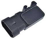
The following links will help you to comparison shop for the MAP sensor of known national brands. You'll avoid buying some knock-off sensor (that may only last a few days) and save a few bucks!:

Disclosure: As an Amazon Associate, I earn from qualifying purchases. Buying through these links helps support this site at no extra cost to you. Thanks for your support —it really means a lot!
If you're not sure if the above MAP sensor fits your particular 2.2L Isuzu Rodeo or Amigo -don't worry. Once you get to the site, they'll make sure the sensor is the right one, if not, they'll find you the right one.
TEST 1: Checking The MAP Signal With A Multimeter
To find out if the MAP sensor on your 2.2L Isuzu Rodeo or Amigo is working correctly, we're gonna' test it while manually applying vacuum to it.
More specifically, we'll connect a vacuum pump to the MAP sensor and watch its signal voltage as we apply and release vacuum:
- As vacuum is applied: the MAP sensor's voltage should decrease.
- As vacuum is released: the voltage should increase again.
If the signal voltage remains stuck at one value while you apply and release vacuum, the MAP sensor is defective. Still, before condemning the sensor, we'll make sure it's receiving its 5-Volt supply and Ground.
If you don't have a vacuum pump, no worries. You can apply vacuum using your mouth and a suitable vacuum hose connected to the sensor.
NOTE: You'll need a multimeter to test the MAP sensor on your Isuzu. If you don't have one, or you're looking to upgrade yours, the following recommendation may help: Tekpower TP8268 AC/DC Auto/Manual Range Digital Multimeter (Amazon affiliate link).
IMPORTANT: The MAP sensor must remain connected to its electrical connector to read its voltage signal. You'll need to use a back-probe on the connector or a wire-piercing probe on the wire to access the MAP signal. You can see an example of this tool here: Goupchn 4mm Banana to Banana Plug Test Leads Kit (Amazon affiliate link)..
OK, let's start:
- 1
Remove the MAP sensor from the intake manifold. If you had to disconnect it from the electrical connector, reconnect it now. The MAP sensor must remain connected to its connector during this test.
- 2
Connect the vacuum pump to the MAP sensor's vacuum inlet port.
- 3
Have your helper turn the ignition key to the ON position, but don't start the engine.
- 4
Set your multimeter to Volts DC mode.
- 5
Connect the black multimeter test lead to the battery negative (-) terminal.
- 6
Connect the red multimeter test lead to terminal 2 of the MAP sensor connector.
Confirm that terminal 2 actually connects to the gray (GRY) MAP signal wire.
NOTE: The MAP sensor must remain connected to its electrical connector so you can measure its signal voltage. - 7
Your multimeter should display approximately 4.5 Volts DC with no vacuum applied to the sensor. If your reading is different, don't worry about it just yet. Continue with the remaining steps.
- 8
Apply vacuum to the MAP sensor until the vacuum gauge reaches 5 in. Hg. As you apply vacuum, the voltage should decrease approximately as follows:
1.) 0 in. Hg ...... 3–4 Volts.
2.) 5 in. Hg ...... 2.4 Volts.
3.) 10 in. Hg .... 1.9 Volts.
4.) 15 in. Hg .... 1.4 Volts. - 9
Release the vacuum you applied. The voltage reading should increase and return close to the value you observed in step 7.
Now let's interpret your test results:
CASE 1: The voltage decreased when you applied vacuum and increased again when you released it. This is the response we're looking for.
Based on this result, the MAP sensor is responding correctly to changes in intake-manifold vacuum. The sensor itself is not defective, so there's no reason to replace it or perform any additional MAP sensor tests.
If the MAP sensor trouble code returns or remains stored, the problem may be somewhere else in the circuit or engine. For additional possibilities, take a look at: MAP Sensor Code Won't Go Away.
CASE 2: The voltage did not decrease or increase as you applied and released vacuum. This result points to a possible defective MAP sensor, but we're not ready to replace it yet.
Before condemning the sensor, we need to confirm that it's receiving its 5-Volt supply and Ground.
Our next test is to check for the MAP sensor's 5-Volt power supply. Go to: TEST 2: Making Sure The MAP Sensor Is Getting 5 Volts.
CASE 3: The multimeter didn't register any voltage. This result does not automatically mean that the MAP sensor is defective.
A missing signal voltage may be caused by a loss of the 5-Volt supply, a missing Ground, or a problem with the sensor's signal circuit. So, before replacing the MAP sensor, we need to check its power and Ground.
Our next test is to check for the MAP sensor's 5-Volt power supply. Go to: TEST 2: Making Sure The MAP Sensor Is Getting 5 Volts.
TEST 2: Making Sure The MAP Sensor Is Getting 5 Volts
If you've reached this test section, your previous test showed that the MAP sensor's voltage signal remained stuck at one value as you applied and released vacuum.
Before we condemn the sensor, we're gonna' verify that it's receiving the proper 5-Volt supply from the PCM.
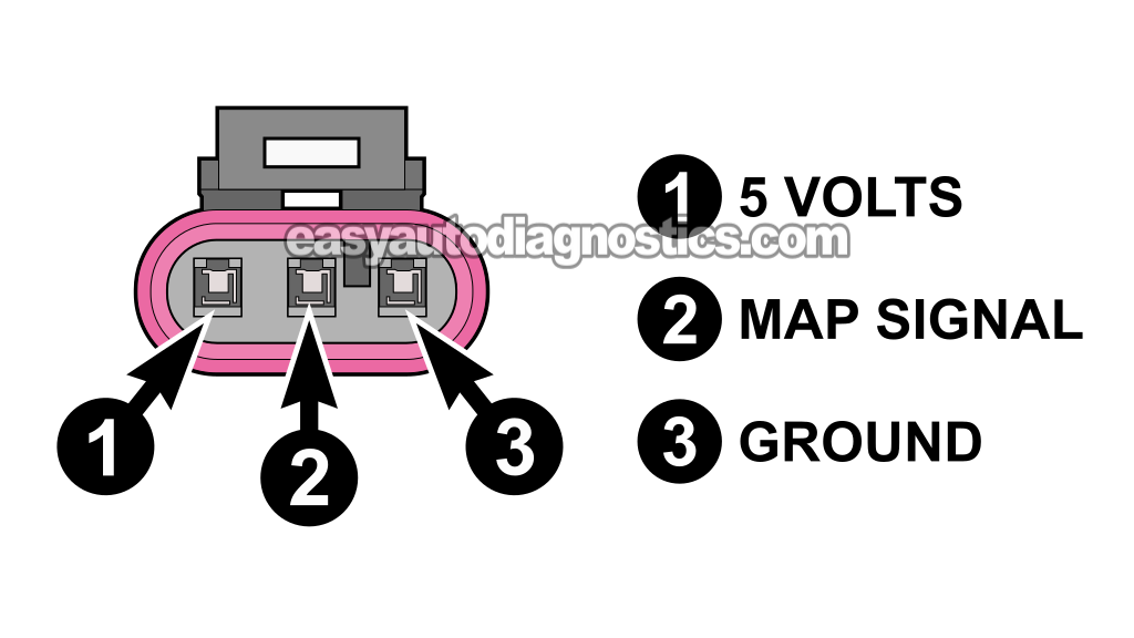
The MAP sensor's 5-Volt supply is carried by the red (RED) wire. This wire connects to terminal 1, identified with the number 1 in the illustration above.
These are the test steps:
- 1
Disconnect the MAP sensor from its electrical connector.
- 2
Have a helper turn the key to the ON position but don't start the engine.
- 3
Place your multimeter in Volts DC mode.
- 4
Connect the black multimeter test lead to the negative (-) battery terminal.
- 5
Gently probe the terminal that connects to the red (RED) wire with the red multimeter test lead.
NOTE: Be careful and don't damage the female terminal. I recommend using a back probe on the connector or a wire piercing probe on the wire. - 6
The multimeter should display 4.5 to 5 Volts on its screen.
Let's see what your test result tells us:
CASE 1: The multimeter displayed 4.5 to 5 Volts. This is the correct result and confirms that the MAP sensor's 5-Volt supply circuit is working.
Now that we know your Rodeo or Amigo's MAP sensor is receiving power, our next step is to verify its Ground circuit. For this test, go to: TEST 3: Making Sure The MAP Sensor Is Getting Ground.
CASE 2: The multimeter did not display 4.5 to 5 Volts. Without this voltage, the MAP sensor cannot operate or produce a valid signal.
The missing voltage is most likely caused by one of the following:
- An open circuit in the red (RED) 5-Volt supply wire between the MAP sensor connector and the PCM.
- A problem inside the PCM. This is possible, but it's a rare failure.
Although diagnosing these two possibilities is beyond the scope of this tutorial, this result tells you that the problem is in the 5-Volt supply circuit and not the MAP sensor itself.
TEST 3: Making Sure The MAP Sensor Is Getting Ground
So far, you have confirmed:
- The MAP signal voltage is stuck or missing as you apply/release vacuum to the sensor (TEST 1).
- The MAP sensor is being supplied with power (TEST 2).
For our last test, we'll make sure the green (GRN) wire is supplying Ground to terminal 3 (of the MAP sensor's 3-wire connector).
To check whether this Ground circuit is working correctly, we'll perform a simple voltage test with a multimeter.
IMPORTANT: If you probe the front of the female terminal, do it very gently with your multimeter test lead. Applying too much force could spread or damage the terminal.
CAUTION: The PCM supplies Ground to the MAP sensor. Be careful not to accidentally short this wire to battery power, since doing so could damage the PCM. The voltage test described below is a safe way to check for the presence of Ground.
Let's get testing:
- 1
Disconnect the MAP sensor from its electrical connector.
- 2
Have a helper turn the key to the ON position but don't start the engine.
- 3
Place your multimeter in Volts DC mode.
- 4
Connect the red multimeter test lead to the positive (+) battery terminal.
- 5
Gently probe the terminal that connects to the green (GRN) wire with the black multimeter test lead.
NOTE: Be careful and don't damage the female terminal. I recommend using a back probe on the connector or a wire piercing probe on the wire. - 6
The multimeter should display 10 to 12 Volts on its screen.
Let's examine your test result:
CASE 1: The multimeter displayed approximately 10 to 12 Volts. This result confirms that the MAP sensor's PCM-supplied Ground circuit is working correctly.
You can conclude that the MAP sensor is defective and needs to be replaced if you have confirmed all three of the following:
- The MAP sensor's signal voltage does not decrease when you apply vacuum (TEST 1).
- The MAP sensor is receiving its 5-Volt supply (TEST 2).
- The MAP sensor is receiving Ground (this test).
CASE 2: The multimeter did not display approximately 10 to 12 Volts. This result indicates a problem with the MAP sensor's Ground circuit.
The problem may be caused by an open circuit in the green (GRN) Ground wire between the MAP sensor connector and the PCM, or by an internal fault in the PCM.
Although diagnosing these possibilities is beyond the scope of this tutorial, don't replace the MAP sensor based on this result. The Ground circuit must be diagnosed and repaired first.
MAP Sensor Code Won't Go Away
If the MAP sensor keeps coming back (after replacing the MAP sensor or confirming it's good), keep in mind that the sensor may only be reporting a problem caused by something else.
A recurring MAP sensor trouble code only happens when the MAP sensor is detecting unusual or unstable intake-manifold pressure. That pressure problem may be caused by an engine mechanical issue, a vacuum leak, or insufficient fuel pressure.
Here are some important things to check:
- Inspect the MAP sensor O-ring: Make sure the O-ring around the sensor's vacuum inlet is not torn, missing, flattened, or damaged. If it doesn't seal properly where the sensor enters the intake manifold, unmetered air can enter the engine and affect the MAP readings.
- Examine the electrical connector: Look for broken plastic, loose terminals, corrosion, or a damaged locking tab. A connector that doesn't hold the terminals securely can cause an intermittent open or short circuit in the MAP signal circuit.
- Check for an intermittent MAP sensor failure: Sometimes a sensor works normally most of the time but fails occasionally. One way to look for this type of problem is to gently tap the sensor with the plastic handle of a screwdriver while applying vacuum and monitoring the signal voltage.
- Watch for an abnormal change: If the voltage suddenly jumps, drops out, or becomes erratic when the sensor is tapped, the sensor may have an internal intermittent fault.
- Test engine compression: Worn valves, damaged piston rings, or another internal engine problem can produce low or unstable intake-manifold vacuum. The PCM may interpret these abnormal readings as a MAP sensor problem.
- Check fuel pressure: A weak fuel pump may not supply enough fuel to maintain the correct air-fuel mixture. Although a fuel pump often fails completely and causes a no-start condition, it can also become weak and cause lean running, hesitation, or unstable engine vacuum. The best way to check for this problem is with a fuel pressure gauge.
More 2.2L Isuzu Rodeo And Amigo Tutorials
You can find a complete list of 2.2L Isuzu Rodeo and Amigo tutorials in this index:
Here's a small sample of the tutorials you'll find in the index:
- How To Test The Fuel Pump (1998-2003 2.2L Isuzu Rodeo, Amigo).
- Common Causes Of Spark Plug Failure (1998-2003 2.2L Isuzu Rodeo, Amigo).
- How To Test The CKP Sensor (1998-2003 2.2L Isuzu Rodeo, Amigo).
- How To Test The TPS (1998-2003 2.2L Isuzu Amigo And Rodeo).

If this info saved the day, buy me a beer!
