This tutorial will help you to test and troubleshoot the ignition coil, the power transistor (ignition control module) and the crankshaft position sensor on the 1990-1994 3.0L V6 Mitsubishi Montero, Mighty Max and Dodge Ram 50. No scan tool required for any of these tests.
Whether your vehicle is suffering a 'no-spark no-start' or a misfire condition, you'll be able to pinpoint the problem to the ignition coil or the power transistor or the crankshaft position sensor (located within the distributor) or the spark plug wires or the distributor cap.
To make sure this test tutorial applies to your specific Mitsubishi or Dodge vehicle, please take a look at the application chart at the bottom of this page (mobile device) or on the left column of this page (PC).
Contents of this tutorial:
- Ignition System Basic Working Theory.
- What Tools Do I Need?
- Power Transistor: Circuit Descriptions.
- Crankshaft Position Sensor: Circuit Descriptions.
- Ignition Coil: Circuit Descriptions.
- TEST 1: Testing For Spark.
- TEST 2: Testing For Spark At The Distributor Cap.
- TEST 3: Ignition Coil High Tension Wire Spark Test.
- TEST 4: Ignition Coil Spark Test.
- TEST 5: Making Sure The Ignition Coil Is Getting Power.
- TEST 6: Verifying The Ignition Coil's Switching Signal.
- TEST 7: Power Transistor Switching Signal Output.
- TEST 8: Making Sure The Power Transistor Is Getting Ground.
- TEST 9: Making Sure The Power Transistor Is Getting An Activation Signal.
- TEST 10: Crankshaft Position Sensor Is Getting Power.
- TEST 11: Crankshaft Position Sensor Is Getting Ground.
- TEST 12: Testing The CKP Signal.
- TEST 13: Testing The CMP Signal.
- Other Common Causes Of A Misfire.
![]() You can find this tutorial in Spanish here: Cómo Probar El Sistema De Encendido (1990-1994 3.0L V6 Mitsubishi Montero) (at: autotecnico-online.com).
You can find this tutorial in Spanish here: Cómo Probar El Sistema De Encendido (1990-1994 3.0L V6 Mitsubishi Montero) (at: autotecnico-online.com).
Ignition System Basic Working Theory
Here's a little working theory of how the ignition system on your Mitsubishi 3.0L V6 creates the spark needed to get your vehicle started and running. In a nutshell, when the ignition system is working properly and you turn the key to crank and start the engine:
- The distributor shaft starts to rotate which causes the crankshaft position sensor to start generating a crankshaft and camshaft position signal, which are sent directly to the fuel injection computer (also known as the PCM).
- With both of these signals (and others from other input sensors), the PCM starts to activate the power transistor (ignition control module) to start switching the ignition coil's primary current (12 Volts) 'ON and OFF'.
- This 'ON/OFF' action is also known as the Switching signal and as you might already know, it's this signal that activates the ignition coil to start sparking away.
- The spark from the ignition coil is delivered to the center of the distributor cap by a high tension wire (spark plug wire).
- The distributor rotor is then fed this spark, which it then distributes to the distributor cap towers.
- From these distributor cap towers, the spark finally reaches the spark plug thru' spark plug wires.
The crankshaft position sensor is at the heart of this type ignition system. Here are some useful facts that you should be aware of about the crankshaft position sensor on your Mitsubishi SUV or pick up:
- The crankshaft position sensor assembly is located in the distributor.
- The crankshaft position sensor assembly produces both a cam position signal and a crankshaft position signal.
- It's an optical type sensor.
- Both sensors produce a digital square wave, if tested on an oscilloscope.
- Both of these signals can also be tested with an inexpensive LED light (which is the method I'll use in this tutorial).
- If it goes bad, then your Mitsubishi SUV or pick up will crank but not start.
The beauty of it all, is that this ignition system is a breeze to test and you don't need any expensive testing equipment to accomplish it!
What Tools Do I Need?
No expensive tools are required to test this type of ignition system. Now, having said that, there are some very specific tools that I recommend to use for the tests. So, here's the basic list:
- A spark tester
- Not just any type of spark tester. I strongly suggest you buy the HEI spark tester (don't have an HEI spark tester? Need to buy one? You can buy it here: OTC 6589 Electronic Ignition Spark Tester).
- Don't use a regular spark plug instead of a dedicated spark tester.
- Don't pull the spark plug wire off of the spark plug as the engine is cranking or running. This will give a false result and/or damage the ignition coil.
- An LED light.
- Click here to see what this looks like: Abe's LED Light Tool.
- Test light.
- Multimeter.
- A cheapie one will do (don't have a digital multimeter? Need to buy one? Click here to see my recommendations: Buying A Digital Multimeter For Automotive Diagnostic Testing).
- Repair manual.
- For whatever other information this article does not cover.
- Helper.
- To help you crank the engine while you observe the LED light (or test light or multimeter).
As mentioned at the beginning of this article, you don't need an automotive scan tool for any of these tests.
Power Transistor: Circuit Descriptions

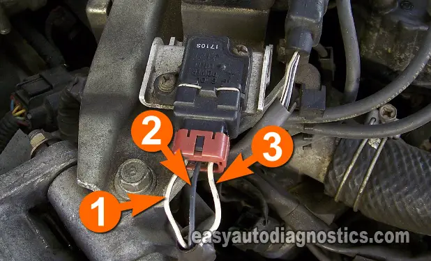
The power transistor (also known as the ignition control module -ICM) has three wires coming out of its connector. Below are the circuit descriptions that I'll be using across this tutorial.
- Circuit 1
- Switching Signal Output (to Ignition Coil) Circuit.
- Circuit 2
- Power Circuit (12 Volts).
- Circuit 3
- Triggering Signal Input Circuit (this signal comes from the fuel injection computer).
IMPORTANT: It will be necessary to test some of these circuits while the engine is being cranked. Be careful, use common sense and take all necessary safety precautions.
Crankshaft Position Sensor: Circuit Descriptions

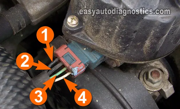
The crankshaft position sensor is a four wire sensor and it is made up of two sensors in one assembly. Below are the circuit descriptions that I'll be using across this tutorial.
- Circuit 1
- Ground Circuit.
- Circuit 2
- Power Circuit (12 Volts).
- Circuit 3
- Crankshaft Position Signal Output.
- Circuit 4
- Camshaft Position Signal Output.
IMPORTANT: It will be necessary to test some of these circuits while the engine is being cranked. Be careful, use common sense and take all necessary safety precautions.
Ignition Coil: Circuit Descriptions

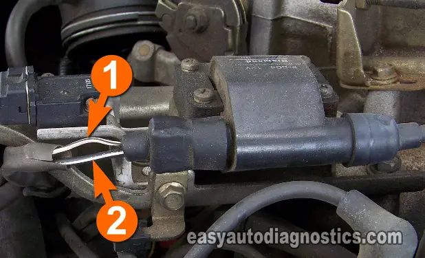
The ignition coil has just two wires coming out of its connector. One feeds it with power (10 to 12 Volts) and the other feeds it the Switching signal. Below are the circuit descriptions that I'll be using in this tutorial.
- Circuit 1
- Switching Signal Input Circuit.
- Circuit 2
- Power Circuit (10 to 12 Volts).
IMPORTANT: It will be necessary to test some of these circuits while the engine is being cranked. Be careful, use common sense and take all necessary safety precautions.

