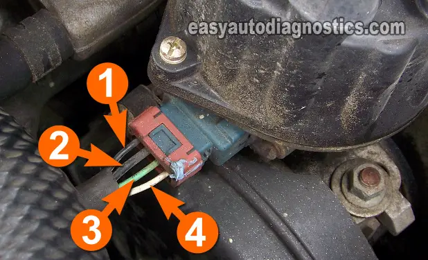
TEST 10: Crankshaft Position Sensor Is Getting Power

The crankshaft position sensor, on your 3.0L V6 equipped Mitsubishi or Dodge vehicle, is located inside the distributor and supplies two different signals to the fuel injection computer.
One signal is a camshaft position (CMP) signal and the other signal is a crankshaft position (CKP) signal.
Both of of these signals can be easily tested with an LED light. Now, before you jump into testing these two signals, you need to verify that it's getting power (10 to 12 Volts).
These are the test steps:
- 1
Disconnect the distributor from its electrical connector.
- 2
Connect the red multimeter test lead to the wire identified with the number 2 in the photo.
- 3
Connect the black multimeter test lead to the battery's negative (-) terminal.
- 4
Have your assistant turn the key to the ON position (no need to crank the engine) as you eye-ball the multimeter.
- 5
The multimeter should register between 10 to 12 Volts DC.
Let's interpret your test result:
CASE 1: The multimeter displayed 10 to 12 Volts DC. This is the correct test result and confirms that the crankshaft position sensor assembly is getting power.
The next test is to verify that the CMP/CKP sensor assembly is getting Ground, go to: TEST 11: Crankshaft Position Sensor Is Getting Ground.
CASE 2: The multimeter DID NOT display 10 to 12 Volts DC. Recheck all your connections and retest.
If the multimeter still does not display the indicated voltage, you'll need to find the cause of this missing voltage, since without power (10 to 12 Volts), the crankshaft position sensor will not function and cause a 'no-spark no-start' condition.
TEST 11: Crankshaft Position Sensor Is Getting Ground

Besides needing 10 to 12 Volts to function, the crankshaft position and camshaft position sensor assembly on your distributor needs Ground.
To check for the presence of this Ground, we're gonna' do a simple multimeter voltage test.
OK, these are the test steps:
- 1
Disconnect the distributor from its electrical connector.
- 2
Place your multimeter in Volts DC mode.
- 3
Connect the black multimeter test lead to the wire identified with the number 1 in the photo.
- 4
Connect the red multimeter test lead directly to the battery's positive (+) terminal.
- 5
Have your assistant turn the key to the ON position as you eye-ball the multimeter.
- 6
The multimeter should register between 10 to 12 Volts DC.
Let's interpret your test result:
CASE 1: The multimeter displayed 10 to 12 Volts DC. This is the correct test result and confirms that the crankshaft position sensor has Ground.
The next step is to verify that it is creating a crankshaft position signal, go to: TEST 12: Testing The CKP Signal.
CASE 2: The multimeter DID NOT display 10 to 12 Volts DC. Recheck all your connections and retest.
If the multimeter still does not display the indicated voltage, this wire has a problem. Repair the cause of this missing Ground in this wire and retest. Repairing the cause of this missing Ground will probably solve your vehicle's 'no-spark no-start' condition.
TEST 12: Testing The CKP Signal

As mentioned earlier, the crankshaft position sensor, on your 3.0L V6 Mitsubishi (or Dodge) vehicle, is two sensors in one. One part produces a crankshaft position (CKP) sensor signal and the other a camshaft position (CMP) sensor signal.
This test section will verify that the crankshaft position sensor part is producing a good signal that the PCM can use to start activating the power transistor and the fuel injectors.
IMPORTANT: If your vehicle starts and runs, then this confirms that the crankshaft position sensor is working and you do not need to test it, therefore, proceed with this test only if you have gotten a no-spark result from all of the spark plug wires (TEST 1) and no spark from the ignition coil tower (TEST 4).
These are the test steps:
- 1
Connect the distributor to its electrical connector.
- 2
Disconnect the ignition coil's electrical connector.
This is an important safety precaution, do not proceed with this test without disconnecting this connector. - 3
Connect the black lead of the LED to the wire identified with the number 3 in the photo.
The distributor must remain connected to its electrical connector for this test, so you will need to either back-probe this wire or use a wire-piercing probe on it (to see an example of a wire-piercing probe, go here: Wire Piercing Probe). - 4
Connect the red lead of the LED to the battery positive (+) terminal.
- 5
Have your assistant crank the engine as you observe the LED light.
- 6
The LED light should flash ON and OFF the whole time that the engine is cranking.
Let's interpret your test result:
CASE 1: The LED light flashed ON and OFF the whole time the engine was cranking. This is the correct test result and tells you that the crankshaft position sensor part of the crank/cam sensor assembly is creating and sending a CKP signal.
The next test is to test the camshaft position sensor part of the crankshaft position sensor, go to: TEST 13: Testing The CMP Signal.
CASE 2: The LED light DID NOT flash ON and OFF the whole time the engine was cranking. Then the crankshaft position sensor is bad and is the cause of the NO SPARK and CRANKS BUT DOES NOT START condition.
Replace the crankshaft/camshaft position sensor assembly in the distributor.

