TEST 4: Testing For Spark At The Ignition Coil Pack (Paired Cylinders)
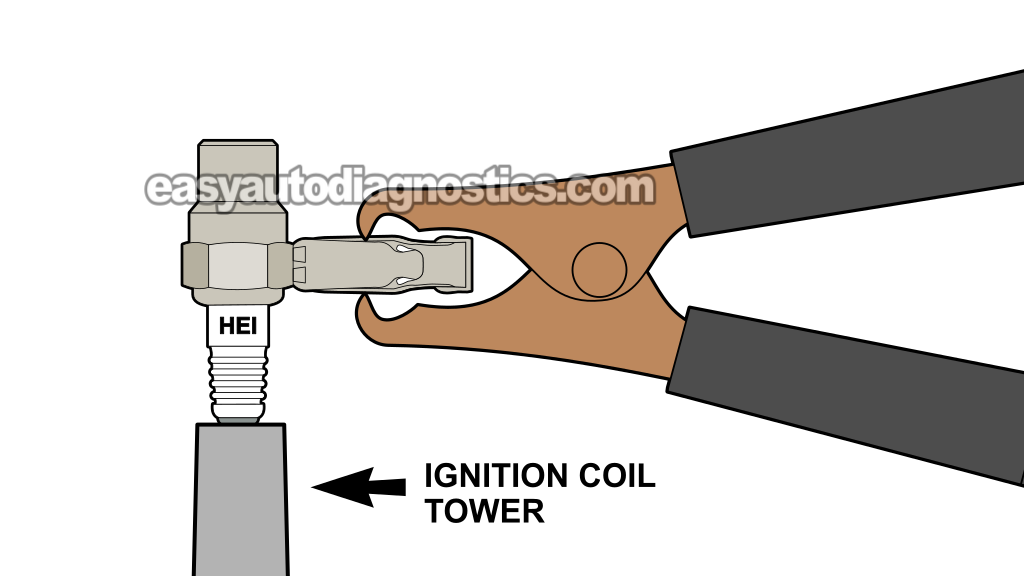
NOTE: This test applies only if TEST 1 showed that two spark plug wires connected to the same cylinder pair (either cylinders 1 and 4 or cylinders 2 and 3) did not produce spark.
Now we need to find out whether the no-spark condition is being caused by the two spark plug wires or by one of the ignition coils inside the ignition coil assembly.
We'll check the two corresponding ignition coil towers for spark, one at a time. These test results will help us determine whether the wires are bad or whether the ignition coil assembly has failed.
Let's get started:
- 1
Remove the spark plug wire that did not spark from the coil pack.
- 2
Place the spark tester directly on the coil pack tower for that wire (see the example in the photo above).
- 3
Connect the spark tester to the battery negative (-) terminal using a battery jump start cable.
- 4
Have your helper crank the engine.
CAUTION: The engine may start, so be careful. - 5
You'll see one of two results: Spark or NO spark.
- 6
Remove the spark tester and reconnect the wire to its coil pack tower.
- 7
Repeat the same spark test on the other coil pack tower —the one that connects to the second non-sparking wire you identified in TEST 1.
Let's take a look at what your test result means:
CASE 1: Only one of the two ignition coil towers produced spark. This result gives us two important pieces of information:
- The ignition coil assembly is bad: The two towers belong to the same waste-spark coil, so both should produce spark. If only one tower sparks, that coil has failed.
- One spark plug wire is also bad: This applies only to the spark plug wire connected to the tower that did produce spark. Since that tower produced spark during this test, but the same wire did not produce spark during TEST 1, that wire is bad.
To take care of the problem, replace the ignition coil assembly and the complete set of four spark plug wires.
CASE 2: Both ignition coil towers produced spark. That's exactly what we want to see. It tells us that the ignition coil assembly is working correctly.
Since neither spark plug wire produced spark during TEST 1, we can conclude that the wires themselves are bad. Replace all four spark plug wires with a new set to solve the problem.
CASE 3: Neither ignition coil tower produced spark. This result usually points to one of two possibilities: the ignition coil assembly has failed, or the coil is not receiving its activation signal from the PCM.
To check for the activation signal or signals, go to: TEST 7: Checking Coil A And B Activation Signals.
TEST 5: Making Sure The Coil Pack Is Getting IGN 12 Volts
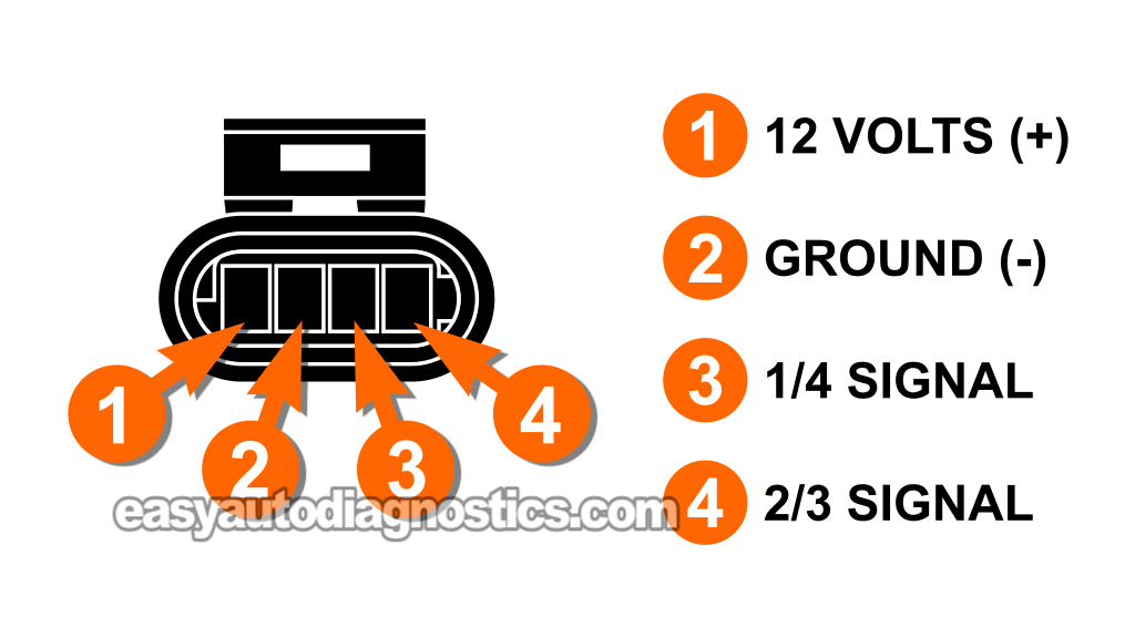
In this test, we're gonna make sure the ignition coil assembly is receiving between 10 and 12 Volts at female terminal 1 of its 4-wire connector.
The wire that supplies this IGN power to terminal 1 is the black with orange stripe (BLK/ORG) wire of coil pack's 4-wire connector.
To check for this power supply, we'll do a simple multimeter voltage test at terminal 1 with the key turned to the RUN position and the engine turned OFF.
NOTE: Be careful when probing the female terminal with your multimeter test lead. If you spread or damage the terminal, the connector may no longer make a proper connection and may need to be replaced.
These are the test steps:
- 1
Disconnect the coil pack from its connector.
- 2
Turn the key to the RUN position but don't crank the engine.
- 3
Put the multimeter in Volts DC mode.
- 4
Connect the black multimeter test lead to the battery negative (-) terminal.
- 5
Gently probe the front of terminal 1 with the red multimeter test lead.
- 6
You should see 10-12 Volts on your multimeter.
Let's find out what your test result means:
CASE 1: Your multimeter showed 10 and 12 Volts at terminal 1. That's exactly what we want to see. This confirms that the ignition coil assembly is receiving its 12-Volt IGN power supply.
Now that we've confirmed the ICM/coil pack assembly is getting power, our next step is to find out whether it's getting Ground. Go to: TEST 6: Making Sure The Coil Pack Is Getting Ground.
CASE 2: Your multimeter DID NOT show 10 and 12 Volts at terminal 1. Check your test connections and repeat the test to make sure the reading is accurate.
If you still don't have IGN power at terminal 1, the ignition coil assembly is not the cause of the no-start problem. Without the 12-Volt supply from the BLK/ORG wire, the ignition coil assembly cannot produce spark.
Your next step is to troubleshoot the missing IGN power supply. Once the 12 Volts are restored to this circuit, the ignition coil assembly can operate and produce spark again.
TEST 6: Making Sure The Coil Pack Is Getting Ground
Up to this point, you have confirmed:
- All four spark plug wires are not sparking (TEST 1).
- The ignition coil is getting 10 to 12 Volts at terminal 1 of its connector (TEST 5).
Our next step is to make sure that the ICM/ignition coil pack assembly is getting Ground, which is supplied by the black (BLK) wire connected to female terminal 2 of the ignition coil pack's 4-wire connector.
This is a chassis Ground, so it's available at all times, regardless of the ignition key's position. To make sure that terminal 2 is providing Ground, we're going to perform a simple multimeter voltage test.
NOTE: Be careful when probing the female terminal with your multimeter test lead. If you spread or damage the terminal, the connector may no longer make a proper connection and may need to be replaced.
Let's get going:
- 1
Disconnect the coil pack from its connector.
- 3
Put the multimeter in Volts DC mode.
- 4
Connect the red multimeter test lead to the battery positive (+) terminal.
- 5
Gently probe the front of terminal 2 with the BLK multimeter test lead.
- 6
You should see 10-12 Volts on your multimeter.
Let's find out what your test result means:
CASE 1: The multimeter showed 10 and 12 Volts at terminal 2. Perfect—that's exactly what we want to see. This confirms that the ignition coil assembly is getting Ground.
Now that we've confirmed the coil pack assembly is getting Ground, our next step is to find out whether the PCM is sending the activation signals needed to trigger both ignition coils inside the assembly (Coil A and Coil B). Go to: TEST 7: Checking Coil A And B Activation Signals.
CASE 2: The multimeter DID NOT show 10 and 12 Volts at terminal 2. Check your test connections and repeat the test to make sure the reading is accurate.
If you still don't have Ground at terminal 2, the ignition coil assembly is not the cause of the no-start problem. Without Ground from the BLK wire, the ignition coil assembly cannot produce spark.
Your next step is to troubleshoot this missing Ground supply. Once Ground is restored to this circuit, the ignition coil assembly can operate and produce spark again.
TEST 7: Checking Coil A And B Activation Signals
In this test section, we're gonna find out whether the PCM is sending the Coil A and Coil B activation signals to the ICM inside the ignition coil assembly. These signals are needed to produce spark for all four cylinders.
Here are the two activation signals we're checking:
- Coil A activation signal: Controls the spark for cylinders 1 and 4.
- Coil B activation signal: Controls the spark for cylinders 2 and 3.
NOTE: The test instructions below explain how to check both signals. However, you may only need to check one of them, depending on the results of the test that sent you here. If the previous test directs you to check the Coil A signal, perform only the Coil A test. If it directs you to check the Coil B signal, perform only the Coil B test. If you're directed to check both signals, perform both tests.
Here are the colors of the two signal wires at the 4-wire ignition coil assembly connector:
- Terminal 3: Red (RED) wire —Coil A activation signal for cylinders 1 and 4.
- Terminal 4: Red with yellow stripe (RED/YEL) wire —Coil B activation signal for cylinders 2 and 3.
CAUTION: Do not use a 12-Volt incandescent test light for this test. These are low-current trigger signals from the PCM to the ICM, not the high-current coil activation signals. Use an LED test light only, because an incandescent test light can load and possibly damage the PCM circuit.
NOTE: If you don't have an automotive 12V LED light, you can buy one here: Oznium Flush Mount 12V LED Light (Amazon affiliate link).
These are the test steps:
- 1
Disconnect the ignition coil assembly's 4-wire connector.
- 2
Connect the red lead of the LED test light to the battery positive (+) terminal.
We're connecting the LED this way because the PCM switches the activation signal toward Ground.
COIL A: Cylinders 1/4 Signal Check:
- 3
Connect the black lead of the LED test light to female terminal 3 of the disconnected connector.
Terminal 3 connects to the red (RED) wire. This is the Coil A activation-signal wire.
NOTE: Be careful when probing the female terminal. If you spread or damage it, the connector may no longer make a proper connection. - 4
Have your helper crank the engine.
- 5
The LED should flash ON and OFF continuously while the engine is cranking.
NOTE: We only need to pay attention to whether the LED flashes during cranking.
COIL B: Cylinders 2/3 Signal Check:
- 6
Connect the black LED lead to female terminal 4 of the connector.
Terminal 4 connects to the red with yellow stripe (RED/YEL) wire. This is the Coil B activation-signal wire. - 7
Have your helper crank the engine again.
- 8
The LED should flash ON and OFF continuously while the engine is cranking.
NOTE: We only need to pay attention to whether the LED flashes during cranking.
Let's find out what your test result means:
CASE 1: The LED light flashed ON and OFF at both terminals while the engine was cranking. This confirms that both activation signals —Coil A and Coil B— are present.
You can condemn the ignition coil assembly and replace it only after confirming all three of these results:
- TEST 1 showed that none of the four spark plug wires produced spark.
- TEST 5 and 6 confirmed that the ignition coil assembly is receiving 12 Volts and Ground.
- This test confirmed that the PCM is sending both the Coil A and Coil B activation signals.
CASE 2: The LED light did not flash ON and OFF at one of the two terminals while the engine was cranking. This confirms that the activation signal for that particular ignition coil is missing.
The most likely cause is an open-circuit in the wire between the ignition coil assembly connector and the PCM connector. Your next step is to check the continuity of the signal circuit between the two connectors and repair any problem you find.
CASE 3: The LED light did not flash ON and OFF at either terminal while the engine was cranking. This tells you that the ignition coil assembly is not receiving either activation signal. Without those signals, the ignition coil assembly cannot produce spark for any of the four cylinders.
When both activation signals are missing, the most likely causes are:
- A bad crankshaft position (CKP) sensor: If the PCM does not receive a CKP signal, it will not trigger the ignition coils.
- A problem with the signal circuits: An open wire, poor connection, or damaged connector can keep the activation signals from reaching the ignition coil pack assembly.
- A PCM problem: This is less common, but a failed ignition-control driver inside the PCM can prevent both activation signals from being produced.
Our next step is to test the CKP sensor and make sure it is generating a signal while the engine is cranking: How To Test The CKP Sensor (1998-2003 2.2L Isuzu Rodeo, Amigo).
Other Things That Can Cause A Misfire
Several different problems can cause a rough-running engine or a cylinder misfire. So, if you've already ruled out the spark plug wires, spark plugs, and ignition coil assembly, this section will give you a few more troubleshooting tips to help you find the real cause of the problem.
-
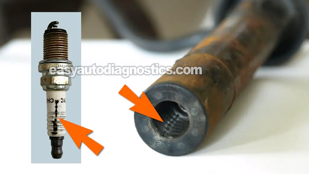
Spark plugs covered in engine oil —A leaking valve cover gasket can allow engine oil to seep into the spark plug tubes and soak the spark plugs and spark plug wire boots. Over time, the oil cooks and creates carbon tracks on the spark plug's porcelain insulator. Those carbon tracks can eventually cause the spark to misfire.
Inspect the inside of the spark plug wire boots and the ceramic insulators of the spark plugs. If you find carbon tracks like the ones shown in the photo above, they can't be cleaned off. You'll need to replace the affected parts and repair the oil leak. Here's a case study on this type of problem:
-
Low or uneven engine compression —On a high-mileage engine, one or more cylinders may develop low compression. When that happens, the engine can run rough at idle or develop a cylinder misfire.
I've written a tutorial that shows you how to perform a compression test and, more importantly, how to interpret the results to identify a weak cylinder causing the rough idle or misfire:
-
Clogged or failed fuel injectors —If one or more cylinders aren't receiving enough fuel (or any fuel at all) they're gonna misfire. You'll need to test the fuel injectors to find out whether one is clogged, electrically failed, or otherwise not delivering fuel correctly.
More 2.2L Isuzu Rodeo And Amigo Diagnostic Tutorials
You can find a complete list of diagnostic tutorials for the 2.2L Isuzu Rodeo and Amigo in this index:
Here's a small sample of the tutorials you'll find:
- How To Test The Fuel Pump (1998-2003 2.2L Isuzu Rodeo, Amigo).
- How To Test Engine Compression (1998-2003 2.2L Isuzu Amigo And Rodeo).
- How To Test The TPS (1998-2003 2.2L Isuzu Amigo And Rodeo).
- How To Test The Fuel Injectors (1998-2003 2.2L Isuzu Rodeo, Amigo).

If this info saved the day, buy me a beer!